Get started with the Dev Board Micro
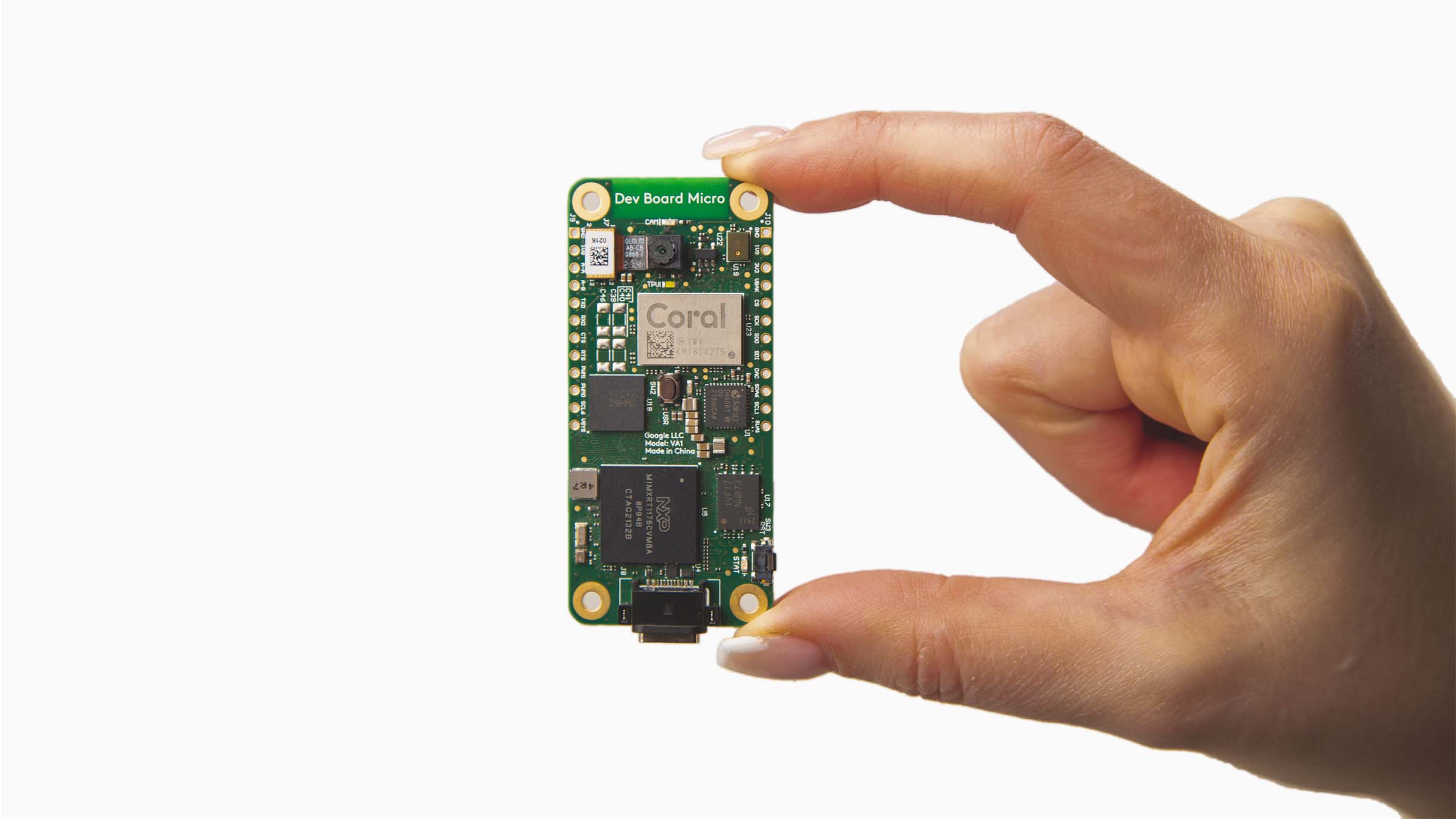
This page shows you how to set up the Coral Dev Board Micro, a microcontroller board that can run TensorFlow Lite models with acceleration on the Coral Edge TPU. With its on-board camera and microphone, this board provides a complete system for embedded machine learning (ML) applications.
Even if you have no experience with microcontrollers, this page explains everything you need to know so you can compile applications and run them on the Dev Board Micro.
1. Gather requirements
- Coral Dev Board Micro
- Linux or macOS computer with Python 3 installed
- USB-C cable (to connect the board to your computer)
Although not required for this setup, you should also get a set of header pins that can be soldered onto the board and a USB-to-TTL serial cable (such as this one by Adafruit) so you can connect to the board's serial console.
2. Get to know the board
Before you get started, let's review the Dev Board Micro hardware and software platform.
The hardware
Aside from the Coral Edge TPU coprocessor for accelerating TensorFlow Lite models, the Dev Board Micro includes the following processor and memory:
- Dual-core i.MX RT1176 MCU
- Cortex-M7 (@800 MHz) and a Cortex-M4 (@400 MHz)
- 2 MB of built-in SRAM
- 64 MB of SDRAM
- More than 1 GB of flash memory
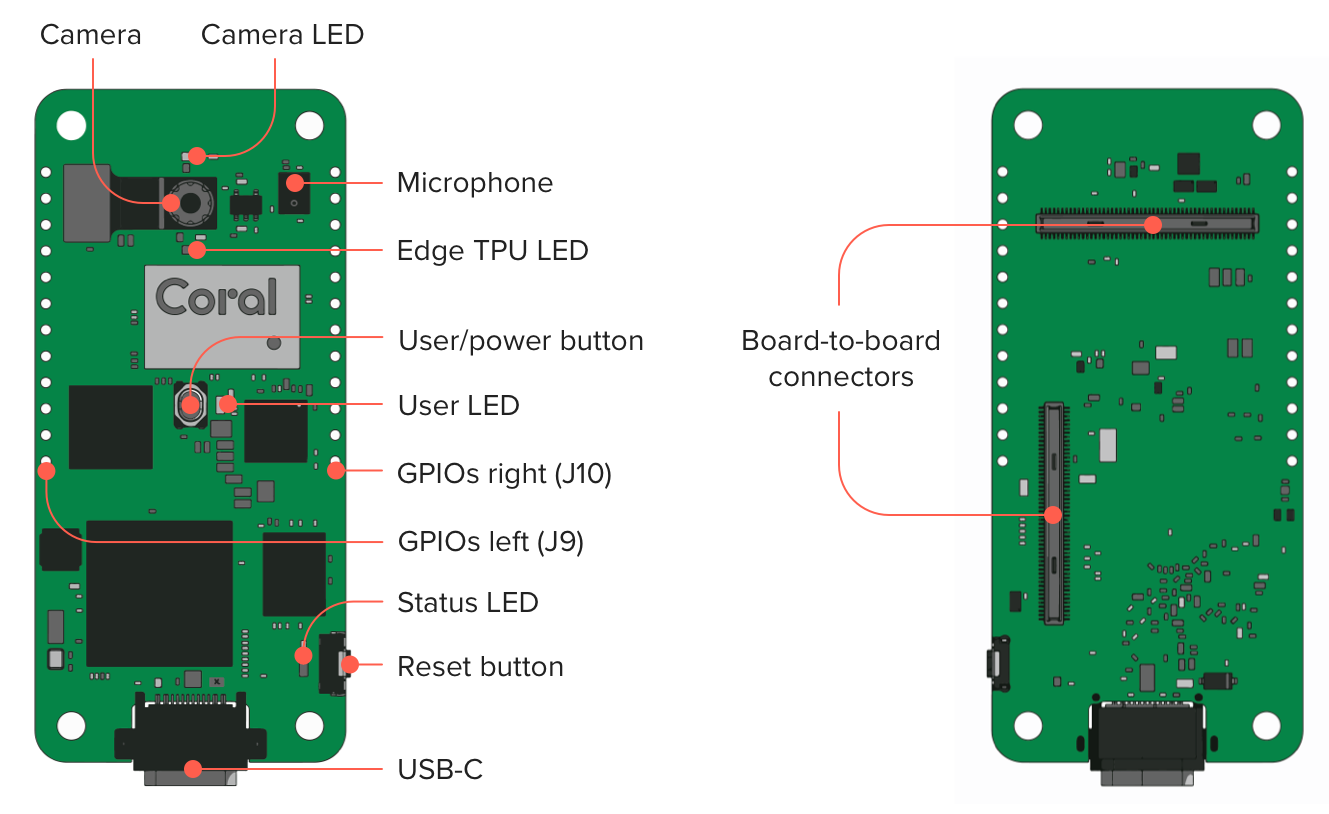
As shown in figure 1, the board includes the following hardware components:
- Color camera (324 x 324 px)
- PDM microphone
- 2 buttons:
- User programmable button (also toggles power with a 7-second hold)
- MCU reset button
- 4 LEDs:
- Camera LED (indicates camera operation)
- Edge TPU LED (indicates Edge TPU operation)
- User LED (application behaviors)
- Status LED (indicates board status)
- 2 GPIO headers with 12 pins (digital, analog, and power pins)
- Board-to-board connectors for add-on boards such as the Coral Wireless Add-on and PoE Add-on
For more hardware details, see the Dev Board Micro datasheet.
The software
Because the main processor is a microcontroller (MCU), the Dev Board Micro runs small programs without a general-purpose operating system (there's no Linux OS like on other Coral boards). The platform we've built for Dev Board Micro is based on FreeRTOS and we also offer compatibility with Arduino. (Alternatively, you can write bare-metal apps with the MCUXpresso SDK, but our documentation covers only FreeRTOS and Arduino.)
All apps are written in C/C++ and the coralmicro API library
provides a variety of APIs
to help you build apps for the Dev Board Micro. For example, it includes APIs
to use the on-board camera, microphone, and GPIO pins, plus APIs to read/write
files, pass messages between the two MCU cores, connect to Wi-Fi
(requires the Coral Wireless Add-on board), and much more.
As for running ML models, you can execute TensorFlow Lite models
either on the MCU or with acceleration on the Edge TPU, using
TensorFlow Lite for
Microcontrollers (TFLM).
The coralmicro library also provides APIs to simplify a lot of this code for
you.
Now let's run some ML models on the board.
3. Boot up for the first time
The Dev Board Micro arrives in the box with a person detection app installed. So let's give it a try:
-
Power the board by connecting a USB cable to the Dev Board Micro and your computer.
After a moment, you should see the green LED above the camera turn on (this indicates the camera is on).
-
Make sure your face is well lit and then hold the board up (USB port facing down) and aim the camera towards yourself. Then aim it away from yourself, and back again.
You should see the green LED near the center of the board turn on when it's facing you, indicating that a person is detected.
This person detection model is extremely small (300 Kb) and it runs entirely on the Cortex-M7 MCU (it does not use the Edge TPU). Its accuracy is limited due to this small size, but it's still very effective, especially when the input image is simple (such as a person against a white background).
This is a good demonstration of what's possible with the MCU alone, but we also offer more powerful models that run on the Edge TPU. So let's set up your development environment so you can flash the board with some other examples.
4. Set up for FreeRTOS development
To start building apps with FreeRTOS, you need to download the Dev Board Micro source code and install some dependencies, as follows:
-
Clone the coralmicro repo and all submodules:
git clone --recurse-submodules -j8 https://github.com/google-coral/coralmicroThis could take a few minutes.
-
Now make sure you have the necessary development tools (such as CMake) by running this setup script:
cd coralmicro && bash setup.shNow you're ready to build and flash some apps to the board.
5. Try the face detection example
The coralmicro repo includes a variety of code examples for you to try. Let's start with the face detection example, which runs a MobileNet face detection model on the Edge TPU:
-
With your terminal still in the
coralmicrodirectory, build all the projects with this script:bash build.sh -
Plug in the board to your computer and verify that it's detected:
lsusbYou should see the board as
Google Inc. Coral Dev Board Micro. -
Flash the face detection example:
python3 scripts/flashtool.py -e detect_facesWhen flashing completes, the board reboots and loads the app. The green Camera LED turns on to indicate the camera is on and the white Edge TPU LED turns on to indicate the Edge TPU is running.
-
Make sure your face is well lit and then hold the board facing you, with the USB port facing down.
The green User LED should turn on when the camera sees your face. As you move the camera toward and away from your face, you should notice this performs faster and more accurately than the first person detection demo.
Now let's make a code change and rebuild the app:
-
Open
coralmicro/examples/detect_faces/detect_faces.ccin an editor. -
Toward the bottom, find the line that declares
CameraFrameFormat, and change the lineCameraRotation::k270toCameraRotation::k0.The default orientation is 270° because the camera module is actually mounted sideways, and a 270° clockwise rotation sets the image straight when the board is standing up. So this change to
k0sets the image back to the camera's natural orientation. -
Save the file and then rebuild the example (from the
coralmicroroot):make -C build/examples/detect_faces -
Now flash the app again. However, you might have noticed last time that loading the
.tflitefile took the most time, but we don't need to load that again because we didn't change it. So add the--nodataflag and flashtool will reload only the program code:python3 scripts/flashtool.py -e detect_faces --nodata
When flashing is done and the app starts, notice that the face detection model now works only when you hold the board sideways so the USB port is on the right. That's because the model was trained to recognize faces in just one orientation.
-e argument
is a shortcut for projects in coralmicro/examples/.
6. Try multi-core model cascading
A unique feature of the Dev Board Micro is its ability to transition between models running on the M4 core and models running on the M7 core and Edge TPU. This is called "multi-core model cascading" because information cascades between models on each MCU core.
To demonstrate this, we created an app that runs a person detection model on the M4, and when it detects a person, it starts a pose detection model that runs on the M7 with acceleration on the Edge TPU.
You can try it on your board as follows:
-
From the
coralmicroroot, just flash app (you already built this project above withbuild.sh):python3 scripts/flashtool.py -a multicore_model_cascadeNote: The flashtool-aargument is a shortcut for projects incoralmicro/apps/. -
For now, leave your board lying down so the camera cannot see you.
-
Once the person detector sees you, it starts the pose detection model, but you need a way to see those results. You have a few options:
-
Stream images over USB:
If you're on Linux, you can see a live stream of camera images with pose overlays by running a client-side Python app:-
First install the required packages:
python3 -m pip install -r apps/multicore_model_cascade/requirements.txt -
Then start the Python app:
python3 apps/multicore_model_cascade/multicore_model_cascade.pyA new window should appear but it will be black because the camera stream appears only when the pose detection model is running.
-
Now hold the board facing you (USB facing down).
When the person detector recognizes you, the green User LED turns on and you should see the pose results in the Python app.
-
-
See results in the serial console:
On any system, you can see person detection scores and the number of detected poses by connecting to the serial console over USB:-
First discover the serial port's USB device name:
On Linux:
ls /dev/ttyACM*On Mac:
ls /dev/cu.usbmodem*This should print just one device file name.
-
Connect to the device shown using a serial console program such as
screenwith a baud rate of 115200. For example:screen /dev/cu.usbmodem1301 115200You should then see a stream of person detection scores, such as:
person_score: -77 no_person_score: 77 -
Now hold the board up to face you (USB facing down).
When the person detector recognizes you, the green User LED turns on and the serial console should show results like this:
person_score: 67 no_person_score: -67
Person detected, let M7 take over.
M4 stopped
M7 Main Task: started
Poses: 1
Poses: 1
The "Poses" are printed at a reduced logging rate to avoid flooding the serial console (the actual inferencing framerate is much faster).
-
-
Stream images over LAN:
If you have the Coral Wireless Add-on or Coral PoE Add-on, you can stream the camera images over your local network. This requires flashing a slightly different version of the app, depending on which add-on board you're using:-
If you're using the Wireless Add-on:
python3 scripts/flashtool.py -a multicore_model_cascade \ --subapp multicore_model_cascade_wifi --wifi_config wifi.txt -
If you're using the PoE Add-on:
python3 scripts/flashtool.py -a multicore_model_cascade \
    --subapp multicore_model_cascade_ethernet
Then follow the same steps to start the client-side Python app, as shown for streaming images over USB, except, you must specify the board's IP address (which is printed in the serial console) with the
--device_ip_addressargument. For example:python3 apps/multicore_model_cascade/multicore_model_cascade.py \ --device_ip_address 192.168.86.42 -
-
To learn how this app runs a TensorFlow model on each MCU core, check out the
source code in coralmicro/apps/multicore_model_cascade/. You can also learn
more in the guide to create a multi-core
app.
Next steps
You've now experienced the basic workflow, but there's much more to learn about building apps for the Dev Board Micro. We recommend the following next steps:
-
Connect to the serial console: The serial console is where you can see the standard output from your apps, which is often helpful for debugging. Although you might have accessed it over USB, as shown above, we recommend that you instead use the UART pins as shown in this guide.
-
Set up your own FreeRTOS project: This guide shows how to set up a new project either as an in-tree project or out-of-tree project that's linked to the coralmicro libraries.
-
Explore the coralmicro API reference: This reference provides details about how to use all the major APIs in the
coralmicronamespace, including GPIO APIs (with board pinout), camera APIs, TensorFlow APIs, and much more. -
Try more code examples: We've created dozens of examples in
coralmicro/examples/to show how you can do everything from blink LEDs, to view the camera stream and run various TensorFlow Lite models. See the usage instructions inside each.ccfile or in the associatedREADMEfile, if provided. -
Connect an add-on board: If you have the Coral Wireless Add-on board or Coral PoE Add-on board, see these guides for setup instructions. The Wireless Add-on board also exposes JTAG pins to enable debugging with GDB.
-
Try Arduino development: If you want to take advantage of the Arduino IDE and the vast Arduino support community when building apps for the Dev Board Micro, checkout this guide.
-
Browse our trained models: Most of these Edge TPU models are compatible with the Dev Board Micro, as indicated by the "Micro" column in each table. However, some models are not compatible because they are too large for the board's memory or because some parts of the model must execute on the MCU and require ops that are not supported by TensorFlow Lite for Microcontrollers.
-
If you want to learn more about building apps with FreeRTOS, see the FreeRTOS concepts documentation.
Also check out the coralmicro source on GitHub.
Flashtool troubleshooting
There are a number of reasons why the flashtool might fail to flash your board or your board might become unresponsive due to a runtime application crash. In almost all cases, these situations are solved by resetting the board into Serial Downloader mode and reflashing the board:
-
Start Serial Downloader (SDP) mode in one of two ways:
- Hold the User button while you press the Reset button.
- Or, hold the User button while you plug in the USB cable.
Release the button when the orange LED turns on.
-
Then try flashing the board again with working code.
If the code has a bug that the compiler cannot catch (such as if the code attempts to load a file that does not exist), the app could crash and the board will become unresponsive (requiring a reflash from SDP mode).
-
If the flashtool succeeds but your board does not automatically restart, reconnect the board power to restart the board. Sometimes this is necessary when the previous image had crashed.
When the board is running the Serial Downloader, lsusb lists the device as:
NXP Semiconductors SE Blank RT FamilyWhereas when the board boots normally, the device appears as:
Google Inc. Coral Dev Board MicroSTATE_FLASHTOOL_ERROR or No devices detected
When flashing the board, if the output includes STATE_FLASHTOOL_ERROR right
before STATE_DONE, or it says only, No Dev Board Micro devices detected,
this is probably because the serial port has failed (the /dev/ttyACM device is
not responding).
To solve it, reset the board to Serial Downloader mode and try flashing again.
Flashing stuck at STATE_CHECK_FOR_SDP
When flashing the board, the flashtool must reset the device into Serial Downloader mode (also known as Serial Download Protocol, or SDP). If this fails, the flashtool stops with this error:
STATE_CHECK_FOR_SDP
Encountered an error during flashing: Unable to find device in SDP mode.
This usually happens for one of two reasons:
- The software currently on the board is in a failed state such that the board cannot respond to the flashtool's request to reset the board into Serial Downloader.
- A computer is currently connected to the serial console via the board's USB
port, which occupies the serial port line (
/dev/ttyACM) that the flashtool needs, so the board does not receive the reset instruction.
To solve it, reset the board to Serial Downloader mode and try flashing again. (Also see how to connect to the serial console with UART instead of using USB.)
If you see it again stuck at STATE_CHECK_FOR_SDP (it should take less than a
second to continue, but will wait 10 seconds for the board to reach SDP),
quickly hold the User button and press Reset to manually enter SDP. Then
flashing should continue normally.
No device found
When flashing the board, if you get a message that says No device found on
<device_name>, it might be because your active user does not belong to the
necessary group to access the board. Check the group owner by listing the device
information. For example, if the device name is ttyACM0:
ls -l /dev/ttyACM0In the output, the group owner is the 4th column item. For example, "dialout" in this case:
crw-rw-rw- 1 root dialout 166, 0 May 26 14:19 /dev/ttyACM0So you must add your username to this group:
sudo usermod -aG dialout $USERThen reboot your computer to apply the group change, and try flashing again.
Is this content helpful?