I/O Pins APIs
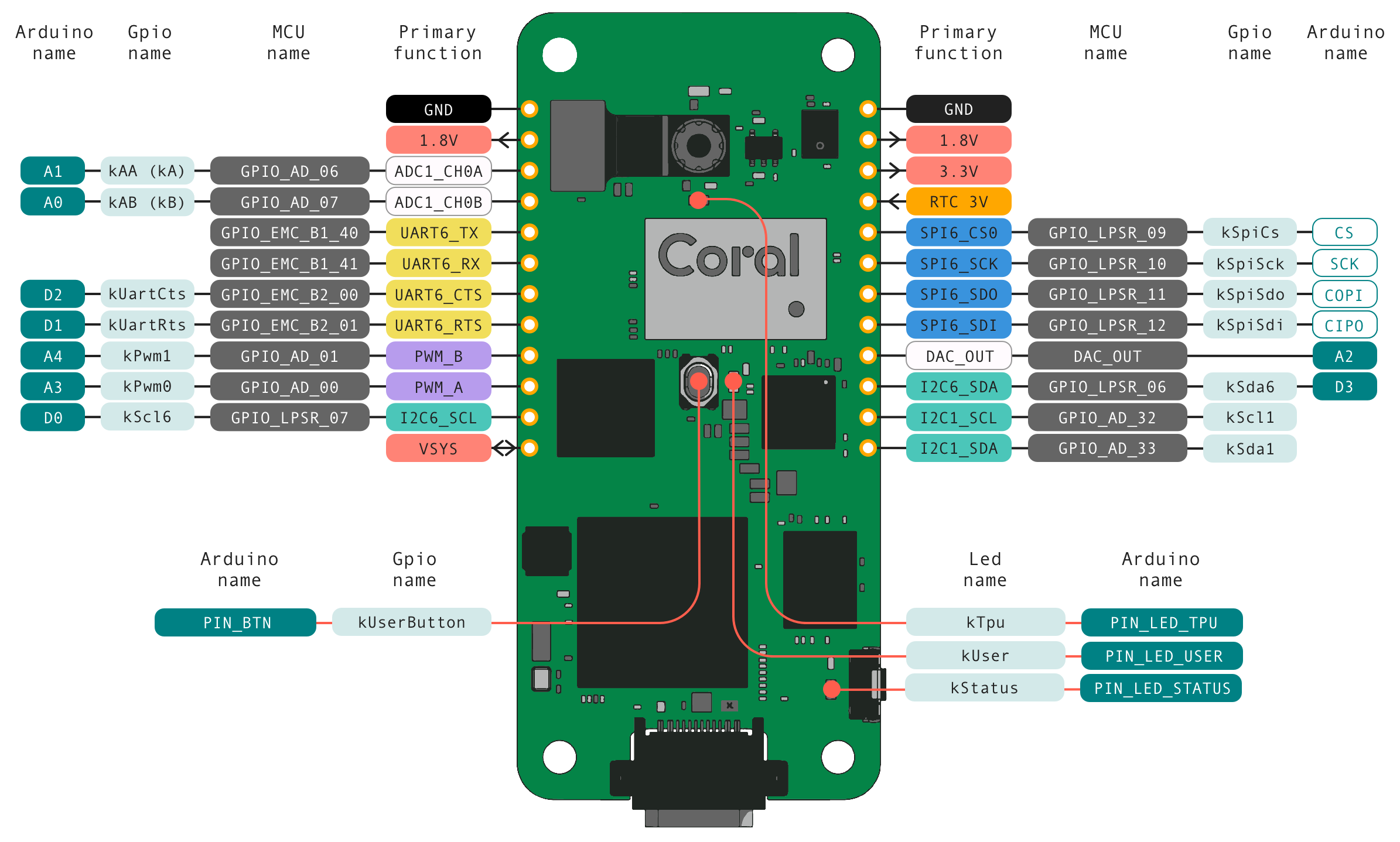
The Dev Board Micro provides access to several digital pins on the two 12-pin headers, including GPIO, PWM, I2C, and SPI. This page describes all the coralmicro APIs available for these pins, plus APIs for the on-board LEDs.
Note
The Dev Board Micro does not include header pins. For development, we suggest you solder header pins to the board with pins facing down (the direction is important to attach to breadboards and for compatibility with Coral cases). If you plan to put the board into a case, be sure your header pins are long enough to be accessible through the case.
Note
All pins are powered by the 1.8 V power rail, and provide a max current of approximately 6 mA on most pins.
Warning
When handling any of these pins, be cautious to avoid electrostatic discharge or contact with conductive materials (metals). Failure to properly handle the board can result in a short circuit, electric shock, serious injury, death, fire, or damage to your board and other property.
GPIO
Almost all digital pins on the 12-pin headers can be used for GPIO (exceptions are the UART TX/RX and DAC pins).
To use a GPIO, specify the GPIO pin name (indicated in figure 1), the
direction, and pull-up or pull-down with
coralmicro::GpioSetMode(). Then set the value or get the value with
coralmicro::GpioSet() and coralmicro::GpioGet().
For example:
extern "C" void app_main(void* param) {
  coralmicro::GpioSetMode(coralmicro::Gpio::kAA, coralmicro::GpioMode::kOutput);
  bool on = true;
  while (true) {
    on = !on;
    coralmicro::GpioSet(coralmicro::Gpio::kAA, on);
    vTaskDelay(pdMS_TO_TICKS(1000));
  }
}
-
namespace
coralmicro Typedefs
-
using
GpioCallback= std::function<void()>¶ The function type required by
GpioConfigureInterrupt().
Enums
-
enum
Gpio¶ Pre-configured GPIO pins.
Values:
-
enumerator
kEdgeTpuPgood¶ Power-good signal from TPU. Active high.
-
enumerator
kEdgeTpuReset¶ Reset input to TPU. Active low.
-
enumerator
kEdgeTpuPmic¶ Power-enable input to TPU. Active high.
-
enumerator
kBtRegOn¶ Enables power regulator on CYW43455 (via B2B connector)
-
enumerator
kUserButton¶ On-board User button. Active low.
-
enumerator
kCameraTrigger¶ Trigger GPIO for single-shot camera capture. Not to be used by apps; instead see
CameraTask::Trigger().
-
enumerator
kCameraInt¶ Input from the camera to indicate motion was detected.
-
enumerator
kAntennaSelect¶ Selects between on-board antenna and antenna connector (for Wi-Fi and BT). Low for internal, high for external.
-
enumerator
kBtHostWake¶ Input from Bluetooth to wake the host, if it was sleeping.
-
enumerator
kBtDevWake¶ Output to Bluetooth, to wake the Bluetooth module from sleep.
-
enumerator
kEthPhyRst¶ Reset signal to the Ethernet PHY. Active low.
-
enumerator
kCameraPrivacyOverride¶ Override for the Camera LED. Low to disable the LED.
-
enumerator
kCryptoRst¶ Reset signal to the A71CH. Active low.
-
enumerator
kLpuart1SwitchEnable¶ Enable signal for the switch that blocks LPUART1 during boot. Set high to allow the LPUART1 signal to pass through.
-
enumerator
kSpiCs¶ SPI6_CS (GPIO_LPSR_09); right header (J10); pin 5.
-
enumerator
kSpiSck¶ SPI6_SCK (GPIO_LPSR_10); right header (J10); pin 6.
-
enumerator
kSpiSdo¶ SPI6_SDO (GPIO_LPSR_11); right header (J10); pin 7.
-
enumerator
kSpiSdi¶ SPI6_SDI (GPIO_LPSR_12); right header (J10); pin 8.
-
enumerator
kSda6¶ I2C6_SDA (GPIO_LPSR_06); right header (J10); pin 10.
-
enumerator
kScl1¶ I2C1_SCL (GPIO_AD_32); right header (J10); pin 11.
-
enumerator
kSda1¶ I2C1_SDA (GPIO_AD_33); right header (J10); pin 12.
-
enumerator
kAA¶ ADC1_CH0A (GPIO_AD_06); left header (J9), pin 3.
-
enumerator
kAB¶ ADC1_CH0B (GPIO_AD_07); left header (J9), pin 4.
-
enumerator
kUartCts¶ UART6_CTS (GPIO_EMC_B2_00); left header (J9), pin 7.
-
enumerator
kUartRts¶ UART6_RTS (GPIO_EMC_B2_01); left header (J9), pin 8.
-
enumerator
kPwm1¶ PWM_B (GPIO_AD_01); left header (J9), pin 9.
-
enumerator
kPwm0¶ PWM_A (GPIO_AD_00); left header (J9), pin 10.
-
enumerator
kScl6¶ I2C6_SCL (GPIO_LPSR_07); left header (J9), pin 11.
-
enumerator
kCount¶ Number of pre-configured GPIOs.
-
enumerator
-
enum
GpioInterruptMode¶ Interrupt modes for use with
GpioConfigureInterrupt().Values:
-
enumerator
kIntModeNone¶ Disables GPIO interrupt.
-
enumerator
kIntModeLow¶ Interrupt when line is low.
-
enumerator
kIntModeHigh¶ Interrupt when line is high.
-
enumerator
kIntModeRising¶ Interrupt when line is rising.
-
enumerator
kIntModeFalling¶ Interrupt when line is falling.
-
enumerator
kIntModeChanging¶ Interrupt when line is either rising or falling.
-
enumerator
kIntModeCount¶ Number of interrupt modes.
-
enumerator
Functions
-
void
GpioSet(Gpio gpio, bool enable)¶ Sets the output value of a GPIO.
- Parameters
gpio – Pin to configure. Only pins in the
Gpioenumeration can be configured with this module. To use a GPIO that is not covered by this module, use the functions inthird_party/nxp/rt1176-sdk/devices/MIMXRT1176/drivers/fsl_gpio.henable – Whether to set the pin to high or low.
-
bool
GpioGet(Gpio gpio)¶ Gets the input value of a GPIO.
- Parameters
gpio – Pin to read.
- Returns
Boolean representing high or low state of the pin.
-
void
GpioSetMode(Gpio gpio, GpioMode mode)¶ Sets the mode of a GPIO.
- Parameters
gpio – Pin to configure.
mode – Mode to configure the gpio as.
-
void
GpioConfigureInterrupt(Gpio gpio, GpioInterruptMode mode, GpioCallback cb)¶ Sets the interrupt mode and callback for a GPIO.
- Parameters
gpio – Pin to configure.
mode – The style of interrupt to sense.
cb – Callback function that will be invoked when the interrupt is raised. This is called from interrupt context, so it should not do much work.
-
void
GpioConfigureInterrupt(Gpio gpio, GpioInterruptMode mode, GpioCallback cb, uint64_t debounce_interval_us)¶ Sets the interrupt mode, callback, and debounce interval for a GPIO.
Example (from
examples/button_led/):[[noreturn]] void Main() { printf("Button LED Example!\r\n"); // Turn on Status LED to show the board is on. LedSet(Led::kStatus, true); printf("Press the User button.\r\n"); // Register callback for the user button. GpioConfigureInterrupt( Gpio::kUserButton, GpioInterruptMode::kIntModeFalling, [handle = xTaskGetCurrentTaskHandle()]() { xTaskResumeFromISR(handle); }, /*debounce_interval_us=*/50 * 1e3); bool on = false; while (true) { vTaskSuspend(nullptr); on = !on; LedSet(Led::kUser, on); } }
- Parameters
gpio – Pin to configure.
mode – The style of interrupt to sense.
cb – Callback function that will be invoked when the interrupt is raised. This is called from interrupt context, so it should not do much work.
debounce_interval_us – Minimum interval in microseconds between repeated invocations of
cb. Useful for cases where the GPIO line could toggle back and forth more frequently than expected, such as a mechanical button.
-
using
PWM
There are two pins pre-configured for pulse-width modulation (PWM) on the left header (pins 9 and 10).
To use a PWM pin, you must first call
coralmicro::PwmInit(). Then specify the PWM settings in an instance of
coralmicro::PwmPinConfig and pass it to
coralmicro::PwmEnable().
Example (from examples/pwm/):
[[noreturn]] void Main() {
  printf("PWM Example!\r\n");
  // Turn on Status LED to show the board is on.
  LedSet(Led::kStatus, true);

  PwmInit();
  PwmPinConfig pin_a_config{.duty_cycle = 20,
                            .frequency = 1000,
                            .pin_setting = PwmPinSettingFor(PwmPin::k10)};
  PwmPinConfig pin_b_config{.duty_cycle = 80,
                            .frequency = 1000,
                            .pin_setting = PwmPinSettingFor(PwmPin::k9)};
  std::vector<PwmPinConfig> configs = {pin_a_config, pin_b_config};
  while (true) {
    PwmEnable(configs);
    vTaskDelay(pdMS_TO_TICKS(1000));
    PwmDisable(configs);
    vTaskDelay(pdMS_TO_TICKS(1000));
  }
}
-
namespace
coralmicro Enums
Functions
-
PwmPinSetting
PwmPinSettingFor(PwmPin pin)¶ Gets the HW settings for a pwm pin.
- Parameters
pin – The pin to get settings for.
- Returns
A setting for the pin or a std::nullopt.
-
void
PwmInit()¶ Initializes the PWM module.
-
void
PwmEnable(const std::vector<PwmPinConfig> &pin_configs)¶ Enables a PWM sub_module with some pins configs.
- Parameters
pin_configs – The list of pin configurations to enable.
-
void
PwmDisable(const std::vector<PwmPinConfig> &pin_configs)¶ Disables a PWM sub_module.
- Parameters
pin_configs – The list of pin configurations to disable.
-
struct
PwmPinConfig¶ - #include <pwm.h>
Represents the configuration for a single PWM pin.
Public Members
-
int
duty_cycle¶ The duty cycle (from 0-100) of the PWM waveform.
-
uint32_t
frequency¶ Frequency in hz.
-
PwmPinSetting
pin_setting¶ The HW setting of the pin to start duty cycle.
-
int
-
struct
PwmPinSetting¶ - #include <pwm.h>
Represents a PWM Pin’s HW setting.
-
PwmPinSetting
ADC / DAC
There are two analog-to-digital converter (ADC) pins pre-configured on the left header (pins 3 and 4) and one digital-to-analog converter (DAC) pin on the right header (pin 9).
To use ADC in either single-ended or differential mode, you must first call
coralmicro::AdcInit() and
coralmicro::AdcCreateConfig(). Then you can read input with
coralmicro::AdcRead().
For DAC, first call coralmicro::DacInit() and
coralmicro::DacEnable(). Then you can write output with
coralmicro::DacWrite().
Example (from examples/analog/):
[[noreturn]] void Main() {
  printf("Analog Example!\r\n");
  // Turn on Status LED to show the board is on.
  LedSet(Led::kStatus, true);

  AdcInit();
  DacInit();
  AdcConfig config{};
  AdcCreateConfig(config,
                  /*channel=*/0,
                  /*primary_side=*/AdcSide::kB,
                  /*differential=*/false);

  // Set the DAC to 0V before we enable it initially.
  DacWrite(0);
  DacEnable(true);
  while (true) {
    uint16_t val = AdcRead(config);
    DacWrite(val);
    printf("ADC val: %u\r\n", val);
  }
}
-
namespace
coralmicro Enums
Functions
-
void
AdcInit()¶ Initializes ADC device.
-
void
AdcCreateConfig(AdcConfig &config, int channel, AdcSide primary_side, bool differential)¶ Populates an
ADCConfigstruct based on the given parameters.- Parameters
config – Configuration struct to populate.
channel – The ADC channel to use (must be less than the max number of channels:
kAdc1ChannelCount).primary_side – In single ended mode, this is the pin that’s connected. In differential mode, this is the pin to use as the primary side.
differential – Whether or not to run the ADC in differential mode.
-
uint16_t
AdcRead(const AdcConfig &config)¶ Reads voltage values from an ADC.
- Parameters
config – ADC configuration to use.
- Returns
Digitized value of the voltage that the ADC is sensing. The ADC has 12 bits of precision, so the maximum value returned is 4095.
-
void
DacInit()¶ Initializes DAC device.
- Parameters
device – DAC to initialize.
-
void
DacEnable(bool enable)¶ Sets the state of the DAC. It is recommended that you set a voltage with
DacWriteprior to enabling the DAC.- Parameters
enable – True enables the DAC; false disables it.
-
void
DacWrite(uint16_t value)¶ Writes voltage values to the DAC.
For example code, see
examples/analog/.- Parameters
value – The voltage value to output. The DAC has 12-bit resolution, so the allowed values are 0 to 4095. The maximum output voltage of the DAC is 1.8V.
Variables
-
constexpr int
kAdc1ChannelCount= 6¶ Available channels on ADC1.
-
struct
AdcConfig¶ - #include <analog.h>
Represents the configuration of an ADC. Each ADC has a 12-bit resolution with 1.8V reference voltage.
-
void
I2C
You can use the board as either the device controller or target, using either of two I2C lines on the 12-pin headers:
I2C1 (I2c::kI2c1)
SDA is pin 10 on the right side
SCL is pin 11 on the left side
I2C6 (I2c::kI2c6)
SDA is pin 12 on the right side
SCL is pin 11 on the right side
Example (from examples/i2c/controller.cc):
void Main() {
  printf("i2c Controller Example!\r\n");
  // Turn on Status LED to show the board is on.
  LedSet(Led::kStatus, true);

  auto config = I2cGetDefaultConfig(coralmicro::I2c::kI2c1);
  I2cInitController(config);

  std::string serial = GetSerialNumber();
  constexpr int kTargetAddress = 0x42;
  int kTransferSize = serial.length();

  printf("Writing our serial number to the remote device...\r\n");
  CHECK(I2cControllerWrite(config, kTargetAddress,
                           reinterpret_cast<uint8_t*>(serial.data()),
                           kTransferSize));
  auto buffer = std::vector<uint8_t>(kTransferSize, 0);

  printf("Reading back our serial number from the remote device...\r\n");
  CHECK(
      I2cControllerRead(config, kTargetAddress, buffer.data(), kTransferSize));
  CHECK(memcmp(buffer.data(), serial.data(), kTransferSize) == 0);
  printf("Readback of data from target device matches written data!\r\n");
}
-
namespace
coralmicro Typedefs
-
typedef lpi2c_slave_config_t
lpi2c_target_config_t
-
typedef lpi2c_slave_transfer_t
lpi2c_target_transfer_t
-
typedef lpi2c_slave_handle_t
lpi2c_target_handle_t
-
using
TargetCallback= std::function<void(I2cConfig*, lpi2c_target_transfer_t*)>
Enums
Functions
-
I2cConfig
I2cGetDefaultConfig(I2c bus)¶ Gets the default configuration for an I2C bus that is available on the header.
- Parameters
bus –
I2cof the desired bus.- Returns
Configuration for using
bus.
-
bool
I2cInitController(I2cConfig &config)¶ Initializes a bus in ‘controller’ mode using the given config.
- Parameters
config –
I2cConfigto initialize the hardware with.
-
bool
I2cInitTarget(I2cConfig &config, uint8_t address, TargetCallback callback)¶ Initializes a bus in ‘target’ mode using the given config.
- Parameters
config –
I2cConfigto initialize the hardware with.address – Address to listen for on the bus.
callback –
TargetCallbackmethod to provide the response data.
-
bool
I2cControllerRead(I2cConfig &config, uint8_t address, uint8_t *buffer, size_t count)¶ Reads data from the configured bus, in
controllermode.- Parameters
config –
I2cConfigfor the configured bus.address – Address of the target device we wish to read from.
buffer – Pointer to a buffer that will contain the receieved data.
count – Number of bytes to read.
-
bool
I2cControllerWrite(I2cConfig &config, uint8_t address, uint8_t *buffer, size_t count)¶ Writes data on the configured bus, in
controllermode.- Parameters
config –
I2cConfigfor the configured bus.address – Address of the target device we wish to write to.
buffer – Pointer to a buffer that contains the data.
count – Number of bytes to write.
-
struct
I2cConfig¶ - #include <i2c.h>
Configuration for an I2C interface.
Public Members
-
LPI2C_Type *
base¶ Base pointer to the I2C peripheral.
-
int
interrupt¶ Interrupt number for the peripheral.
-
std::array<uint32_t, 5>
sda¶ IOMUXC configuration for the SDA pin.
-
std::array<uint32_t, 5>
scl¶ IOMUXC configuration for the SCL pin.
-
bool
controller¶ True if the interface will be the controller; false if target.
-
lpi2c_rtos_handle_t
controller_handle¶ Handle for LPI2C RTOS driver.
-
lpi2c_master_config_t
controller_config¶ Configuration for LPI2C in controller mode.
-
lpi2c_target_config_t
target_config¶ Configuration for LPI2C in target mode.
-
lpi2c_target_handle_t
target_handle¶ Handle for LPI2C driver in target mode.
-
std::function<void(I2cConfig*, lpi2c_target_transfer_t*)>
target_callback¶ Callback function for sending data in target mode. Note: this will be called in interrupt context, so this can’t take too long to execute.
-
uint32_t
clk_freq¶ Root clock frequency of the I2C module.
-
LPI2C_Type *
-
typedef lpi2c_slave_config_t
SPI
There is one serial peripheral interface (SPI) bus pre-configured on the right header:
Pin 5 is chip select
Pin 6 is clock
Pin 7 is data out
Pin 8 is data in
Example (from examples/spi/):
void Main() {
  printf("SPI Example!\r\n");
  // Turn on Status LED to show the board is on.
  LedSet(Led::kStatus, true);

  constexpr int kTransferBytes = 256;
  std::array<uint8_t, kTransferBytes> tx_data{};
  std::array<uint8_t, kTransferBytes> rx_data{};
  for (int i = 0; i < kTransferBytes; ++i) {
    tx_data[i] = i;
    rx_data[i] = 0;
  }

  SpiConfig config{};
  SpiGetDefaultConfig(&config);
  CHECK(SpiInit(config));
  CHECK(SpiTransfer(config, tx_data.data(), rx_data.data(), kTransferBytes));
  printf("Executing a SPI transaction.\r\n");
  for (int i = 0; i < kTransferBytes; ++i) {
    CHECK(tx_data[i] == rx_data[i]);
  }
  printf("Transaction success!\r\n");
}
-
namespace
coralmicro Functions
-
void
SpiGetDefaultConfig(SpiConfig *config)¶ Gets the default configuration for using SPI on the device header.
- Parameters
config –
SpiConfigto populate with default values.
-
bool
SpiInit(SpiConfig &config)¶ Initializes SPI with a given configuration.
- Parameters
config –
SpiConfigto initialize hardware with.- Returns
True on success; false otherwise.
-
bool
SpiTransfer(SpiConfig &config, uint8_t *tx_data, uint8_t *rx_data, size_t size)¶ Executes a transfer over SPI with the given configuration.
- Parameters
config –
SpiConfigto use to execute the transaction.tx_data – Pointer to data that will be sent.
rx_data – Pointer to a buffer to contain received data (may be NULL).
size – Number of bytes to transfer.
- Returns
True on success; false otherwise.
-
struct
SpiConfig¶ - #include <spi.h>
Configuration for a SPI interface.
Public Members
-
LPSPI_Type *
base¶ Base pointer to the SPI peripheral.
-
int
interrupt¶ Interrupt number for the peripheral.
-
std::array<uint32_t, 5>
cs¶ IOMUXC configuration for CS pin.
-
std::array<uint32_t, 5>
out¶ IOMUXC configuration for SDO pin.
-
std::array<uint32_t, 5>
in¶ IOMUXC configuration for SDI pin.
-
std::array<uint32_t, 5>
clk¶ IOMUXC configuration for SCK pin.
-
lpspi_rtos_handle_t
handle¶ Handle for LPSPI RTOS driver.
-
lpspi_master_config_t
config¶ Config for LPSPI module.
-
uint32_t
clk_freq¶ Output clock frequency.
-
LPSPI_Type *
-
void
LEDs
These APIs allow you to control the LEDs built into the Dev Board Micro, indicated in figure 1.
To control other LEDs attached to GPIO pins, you must instead use the GPIO APIs, but beware that a GPIO pin alone is not strong enough to drive an LED.
Note
The camera LED is not available with this API because it’s intended to give people awareness that images are being captured by an image sensor for storage, processing, and/or transmission. We strongly recommend this LED behavior remain unchanged and always be visible to users.
Example (from examples/blink_led/):
[[noreturn]] void Main() {
  printf("Blink LED Example!\r\n");
  // Turn on Status LED to show the board is on.
  LedSet(Led::kStatus, true);

  bool on = true;
  while (true) {
    on = !on;
    LedSet(Led::kUser, on);
    vTaskDelay(pdMS_TO_TICKS(500));
  }
}
-
namespace
coralmicro Enums
Is this content helpful?